More than half of construction companies now use Building Information Modeling (BIM) on their projects, which makes coordinated MEP drawings an industry standard.
The meaning of MEP drawings is to show the layout and installation details for a building’s mechanical, electrical, and plumbing systems. They turn engineering designs into clear instructions for construction teams. Architects, contractors, engineers, and design-build teams all rely on them to plan, install, and inspect systems.
Precise MEP drawings help get permits, prevent conflicts between systems, control costs, and keep construction on schedule. MEP architectural drawings specifically show how these systems fit within the building’s structure, helping architects coordinate with mechanical, electrical, and plumbing layouts.
This guide covers what MEP drawings include, the types used in a project, and tips for reading and managing them. You will also see how accurate drawings make coordination easier, reduce mistakes, and support smoother construction.
Why Does Accuracy in MEP Drawings Matter for Permit Approval?
Accurate MEP drawings make it easier to get building permits. They show where equipment goes, how systems are sized, and how routes are planned. Clear drawings help reviewers confirm that the design follows local and national codes.
Mistakes or missing details in drawings slow the permit process because reviewers must request corrections. This can delay the schedule and increase costs. Studies show that 52% of rework in construction comes from poor project data and miscommunication, highlighting why precise drawings are so important.
Accurate drawings also help avoid conflicts between systems. Inspectors can see that ventilation, electrical, plumbing, fire protection, and energy systems are coordinated properly. Drawings that match the design and codes reduce rejected work, redesigns, and field changes. This keeps the permit process moving faster and the project on track.
What are the Types of MEP Drawings?
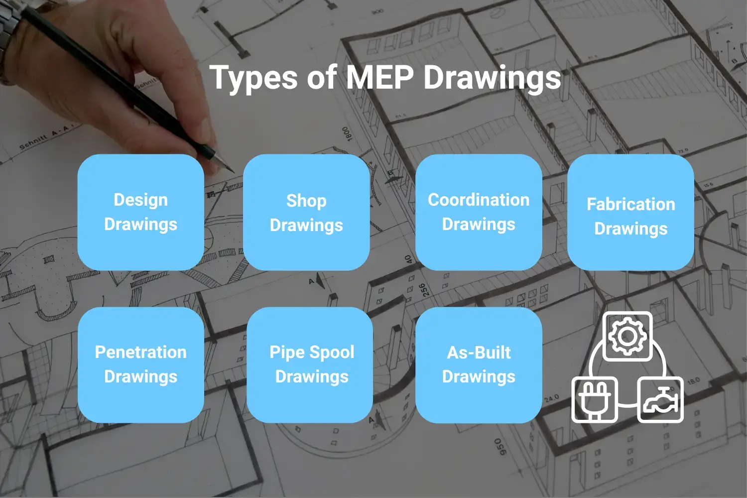
Construction projects use several types of MEP drawings. Each type serves a specific purpose, from early planning to documenting completed work. Teams generally follow a step-by-step process when using them. They start with design drawings, then move to shop and coordination drawings. After that, they do fabrication and field drawings, and finish with as-built drawings.
Design Drawings
Design drawings are the starting point of any MEP project. Architects and engineers use them to outline the overall layout and how different systems should function. Design drawings are used for permitting and help the entire team prepare for bidding.
They typically move through several stages: schematic design, design development, and finally construction documents.
Although construction documents include more than enough detail for approvals, they don’t go deep enough to guide actual fabrication or installation. That level of precision comes later.
Shop Drawings
Contractors and fabricators create shop drawings after design drawings. They show exact measurements, materials, routing, connections, and installation steps. These drawings show actual site conditions. Teams use them to make sure installations follow the design and meet code.
Coordination Drawings
Coordination drawings bring all systems together in one view. They show mechanical, electrical, plumbing, fire protection, structural, and architectural elements to prevent conflicts. At this stage, engineers often use BIM models to detect clashes in three dimensions. These drawings reduce rework and keep the project on schedule.
Fabrication Drawings
Fabrication drawings show how to make parts before bringing them to the site. These parts include duct sections, pipe assemblies, and equipment skids. The drawings show sizes, materials, weld points, and how parts connect. Teams use these drawings to build parts effectively and efficiently.
Penetration Drawings
Penetration drawings show where pipes, ducts, wires, and cables go through walls, floors, and ceilings. They show sleeve sizes, fire-stopping rules, and limits from the building structure. These drawings help avoid mistakes that can damage the building or create safety problems.
Pipe Spool Drawings
Pipe spool drawings divide piping into sections with all fittings, valves, supports, and connections. They often include isometric views to make field assembly easier. Spool drawings reduce errors, save time, and speed up installation.
As-Built Drawings
As-built drawings show how the systems were actually installed. They include all changes made in the field. These drawings serve as a reference for maintenance, repairs, renovations, and future upgrades.
How to Read and Interpret MEP Drawings
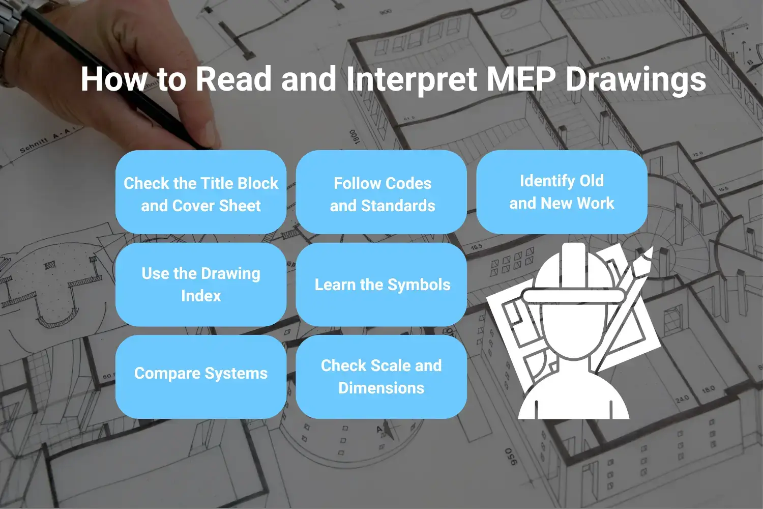
Reading MEP drawings becomes easier when you follow a structured approach. Each step focuses on key parts of the drawings to avoid mistakes.
Check the Title Block and Cover Sheet
Start with the title block. It shows the project name, sheet purpose, scale, and responsible parties. Look at the cover sheet for symbol legends, notes, abbreviations, and the drawing index. These explain how the rest of the drawings are organized.
Use the Drawing Index
Open the index to see all sheets. Mechanical sheets often start with “M,” electrical with “E,” and plumbing with “P.” Use the index to quickly find the sheet you need.
Learn the Symbols
Symbols show vents, switches, pipes, valves, and equipment. Check the legend carefully. Compare symbols with equipment schedules to confirm sizes, models, and locations.
Check Scale and Dimensions
Look at the scale on each sheet. Use the listed dimensions rather than measuring printed drawings. This ensures correct spacing and avoids clashes.
Compare Systems
Review the mechanical, electrical, and plumbing drawings together. Examine walls, ceilings, shafts, and shared spaces. Spot conflicts before installation.
Follow Codes and Standards
Check the building codes and safety standards noted on the drawings. Follow these rules to make sure installations meet requirements.
Identify Old and New Work
Drawings distinguish existing systems from new work using line types, colors, or hatching patterns. Pay attention to these differences to avoid demolition errors and integrate new systems correctly.
What are MEP Drawing Symbols?
Mechanical Symbols
Mechanical symbols show how air and water move in the building. They mark supply and return vents, duct sizes, and airflow direction. Symbols show major equipment, such as air handling units, fan coils, boilers, chillers, and heat pumps. They also include valves, dampers, thermostats, sensors, and the paths of pipes. These symbols help engineers and installers see how each component fits and connects in the space.
Electrical Symbols
Electrical symbols show where electricity goes and how devices connect. They show outlets, switches, lights, panels, transformers, and paths for wires or conduits. They also show junction boxes, pull boxes, emergency lights, and fire alarm locations. Electricians use these symbols to plan circuits, avoid conflicts, and install equipment the right way.
Plumbing Symbols
Plumbing symbols show water, drainage, and gas systems. They show hot and cold water lines, pipes for toilets and vents, floor drains, roof drains, and cleanouts. They also show valves, backflow preventers, water meters, gas pipes, and water heaters. Plumbers use these symbols to put pipes in the right place and follow building codes.
What are the Common Mistakes When Working with MEP Drawings?

Not Checking Drawings Before Bidding
Many people do not check all MEP drawings before sending a bid. This can cause wrong cost estimates and delays. It can also create arguments with clients or subcontractors. If you check every sheet, it will help you avoid these problems.
Ignoring Specifications
Some teams only look at the drawings and skip the specifications. Specifications show what materials to use, how to install them, and the quality expected. Missing this information can lead to wrong parts or methods. Reading both drawings and specs will keep the work correct.
Skipping Code Compliance Verification
If you assume the drawings follow local building codes, you can run into problems. Field conditions or new rules may require extra checks. Ignoring the codes can cause failed inspections and added costs. Make sure everything meets the codes to avoid these issues.
Overlooking Coordination Notes
Coordination notes explain how different trades work together. If you ignore them, it can cause clashes between mechanical, electrical, and plumbing systems. This can create rework and delays. To keep the installation smooth, follow the notes.
Using Outdated Drawings
Old drawings may show wrong dimensions or system layouts. They can waste time, materials, and labor. They can also cause expensive errors. Always check and use the latest drawings to avoid these problems.
Delaying RFIs
Another common mistake is waiting too long to ask questions about unclear drawings. This can cause errors and slow the project. Sending RFIs early gives everyone the right information. Asking questions on time keeps the project on track.
Best Practices for Managing MEP Drawings
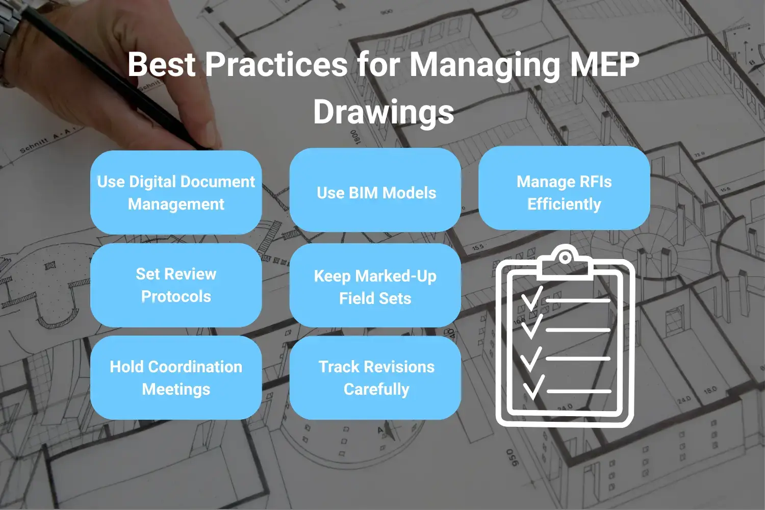
- Use Digital Document Management: Store all drawings in a cloud system. Control which version is current and give field teams mobile access. This stops confusion from old paper prints and ensures everyone uses the same information.
- Set Review Protocols: Hold structured reviews before construction starts. Include all trades and designers. This helps catch conflicts and mistakes early, before work begins.
- Hold Coordination Meetings: Meet weekly or every two weeks to check upcoming work. Discuss potential clashes and confirm how systems will be installed. These meetings help teams work together smoothly.
- Use BIM Models: Use BIM models for clash detection, spatial checks, and planning prefabricated parts. Extract drawings, quantities, and schedules from coordinated models. This makes installation faster and reduces errors.
- Keep Marked-Up Field Sets: Record any field changes, adjustments, or deviations in marked-up drawings. Use these to produce correct as-built documents later. This ensures records reflect what was actually installed.
- Track Revisions Carefully: Share updates as soon as drawings change. Keep a log of dates, recipients, and confirmations. This makes sure everyone works from the latest drawings.
- Manage RFIs Efficiently: Set clear rules for sending, routing, and answering RFIs. Track how fast questions are answered and solutions given. Look for patterns that show repeated drawing issues.
MEP Drawing Services from YA Creative Design Partners
YA Creative Design Partners delivers full MEP engineering services for commercial, multifamily, institutional, and industrial projects. We support every stage, from initial design through construction closeout.
Our team creates coordinated MEP drawings using BIM technology and standard drafting methods. We create complete sets, including floor plans, riser diagrams, equipment schedules, detail sheets, and specifications. These drawings meet permitting requirements and help construction run smoothly.
Our mechanical engineers design HVAC systems with layouts, duct and pipe routing, control systems, and energy compliance documentation. Electrical engineers create power distribution plans, lighting layouts, panel schedules, low-voltage systems, and life-safety documentation. Plumbing engineers handle water supply, drainage, fire protection, and specialty systems that integrate with mechanical and electrical designs.
By working alongside structural and civil engineers, our team produces highly coordinated drawings that reduce field conflicts. Our BIM-based process allows early clash detection, supports prefabrication, and produces models ready for construction.
We follow U.S. building codes and local permitting standards. This makes sure drawings move easily through plan review and meet all technical requirements. During construction, we support contractors with RFIs, submittal reviews, and site observations. Our team also provides commissioning coordination to make sure systems are installed correctly and perform as intended.
Whether your project is new construction, renovation, tenant improvement, or an addition, YA Creative Design Partners delivers MEP drawings that keep projects on schedule, on budget, and functioning properly.
Conclusion
MEP drawings affect permits, budgets, schedules, and project quality. They turn engineering designs into instructions, show how systems connect, and provide a record for building operations.
BIM technology improves MEP coordination by detecting clashes, showing systems clearly, and helping teams work together, which reduces mistakes on site.
Working with experienced MEP engineers ensures drawings are complete, coordinated, and ready for construction. YA Creative Design Partners provides MEP drawing services with technical knowledge, local code expertise, and BIM coordination. Contact us to see how we can help with your next project.
Frequently Asked Questions
What is the difference between design drawings and shop drawings?
Design drawings are made by engineers to show general layouts and design intent for permits. Shop drawings are created by contractors and fabricators with precise details for actual installation, based on site conditions.
Why are MEP drawings important for construction projects?
MEP drawings help teams get permits, estimate costs accurately, coordinate trades, prevent clashes in the field, and ensure systems are installed correctly.
How do I read MEP drawing symbols?
Start with the symbol legend on the cover sheet or first page. Match symbols on plans with the equipment schedules to understand sizes, models, and locations.
What software is used to create MEP drawings?
Common software includes Autodesk Revit for BIM design, AutoCAD MEP for 2D and 3D drafting, Navisworks for coordination and clash detection, and cloud platforms like BIM 360 for collaboration and document management.
When are as-built MEP drawings required?
As-built drawings show how systems were actually installed. They are usually submitted at project completion and help with maintenance, repairs, and future renovations.
How does BIM improve MEP drawing coordination?
BIM allows 3D modeling, automatic clash detection, better visualization, accurate quantity takeoffs, and easier collaboration. It also helps plan prefabrication and modular construction.